The task of illuminating exterior signs or billboards is a little abstract for many new AGi32 users. Most understand the concepts but find it difficult to conceptualize the model in software. There are several ways to approach the problem but I’m going to show you what I believe to be the easiest and most informative.
STEP 1 – Build the sign.
I prefer to use an object in AGi32 that is the physical size of the sign. This can be handy for a number of reasons that will become obvious as we progress.
Let’s assume our sign is a standard billboard (Bulletin in advertising parlance) at 14’ tall by 48’ wide. Signs of other sizes will be a similar exercise.
In AGi32 locate the Rectangular object command.
You should be in Plan view. Enter a Z height of 14’ in the dialog. The reflectance doesn’t really matter as there won’t be adjacent surfaces and you may not know what the sign content will be. Leave it at 50%.

Exit the dialog and draw the sign as you would see it from the top (in Plan view). Set your Snap at 0.5 and make it 6” thick.

The base of the sign will be at Z=0 which is fine, the height of the sign above the ground is usually not relevant as the luminaires are typically mounted on the sign structure. If that is not the case you would need to locate the base of the sign at the proper Z-coordinate (enter the Z of the base in the lower right corner of the screen when drawing, or just move it in elevation view using the move command).
STEP 2 – Place calculation points on the face of the sign.
This is easy using AGi32’s automatic placement command. This is one of the reasons why it’s nice to use an object for the sign structure.
From the Calculations toolkit click on the Automatic Placement button.
Select the sign.
Notice that the selected surface (blue highlight) is the back of the sign. You can tell by observing the orientation of the X-axis.

Use the “Next Surface” icon to move the blue highlight to the front of the sign (2 clicks).
Now set the calculation point spacing to 2’ in each direction.

Click OK to exit the dialog.
Click on the Isometric view button to see your work so far. I added the dimension using the drawing tools in plan view.

STEP 3 – Define the luminaire to be used.
First, we need to shop for a sign light.
From the Luminaire toolkit select the Define button.
Click on the Instabase button.
Load the McGraw Edison data from Eaton (Cooper).
Enter the text “sign” (no quotes) in the Text Search field as shown below.
Run the search. There are 6 sign lights in the McGraw Edison database.
Open the MAQ Marquis node.
Select the file: MAQ-B120-7-LED-E1-SN.IES
Now click the Download to AGi32 button link.

AGi32 presents the Smart Symbols dialog. Select the BOX UP symbol (floating mounting type is the default).
Enter a light loss factor of 0.8 and click the Add/Redefine button.
Before you close the Define dialog notice the photometric distribution (click the MORE button to see the dialog below). This fixture is a little unusual as it was tested in its standard operating position (on its back facing up). This is often typical for sign lights.

If you are struggling to understand the intensity curves, watch our video on understanding polar curves of luminous intensity.
Exit the Define dialog. Understanding the photometric information is important so we can apply the luminaire correctly in the model.
STEP 4 – Determine the lighting criteria.
I was unable to find illuminance recommendations for outdoor advertising in the IES document library or handbook. Searching the Internet I was able to turn up a very wide variety of recommendations from manufacturers , DOT’s and environmental stakeholders. They range from 3 fc to 100 fc average. I know there is no client who will pay to have a bulletin illuminated to 3 fc, and 100 fc is most likely excessive. Examining examples from manufacturers I selected an average of 50 fc with Maximum/Minimum ratio of better than 6:1.
A back of the envelope lumen calculation tells us we will most likely need four luminaires.
#fixtures = (50 fc)(14×48 sq.ft) / (19691 lms)(.8 LLF)(CU guessed at .5) = 4.26
STEP 5 – Place the luminaires in the model.
Manufacturers recommend slightly different luminaire locations depending on their product’s photometric distribution. It is common to see sign lighting products like our selection mounted 1-3 feet below the sign with 4-6 feet setback. You may need to do a little trial and error to determine the best position when working on your own applications.
For the purposes of this blog post, I have placed the luminaires 3’ below the sign and 6’ back.

You can do this by entering a negative three (-3) in the MH cell of the toolkit, followed by an Orient value of 90 degrees (the luminaires are pointing North).
In the drawing area, place the luminaires at the positions shown by using an array along a line or simply set the cursor Snap to 6 and click them in using the Locate command. They are spaced 12’ apart with end spacing of 6’.
If you use an array line, here are your dialog inputs.

With the luminaires in place, you can enable the photometric web on one of the luminaires for a better understanding of how the light distribution fits the application.
Select the Settings for the Photometric Web command from the Luminaire toolkit.

In the Settings dialog:
- Remove the check from the Temporary box
- Check the Photometric Web
- Select “Use Actual Angles” for the best representation of the photometry

Now select the Photometric web button (not Settings) and click on one of the luminaires to display the photometric web.
STEP 6 – Calculate the results.
Select the Full Radiosity Mode for calculation.
From the Calculation menu enable Adaptive Subdivision and change the Minimum Element Area to 0.15.

This will allow the adaptive process to divide the elements (receivers of light) into smaller pieces more quickly than the default setting which makes for a finer luminance gradient in the visualization.
Click on the Calculate button to compute the results.
Let’s look at the point-by-point in Model mode by going to Elevation View looking North.
Select the Elevation View North button and then click anywhere along the coordinate value of Y=-6 (the plane of the luminaires).
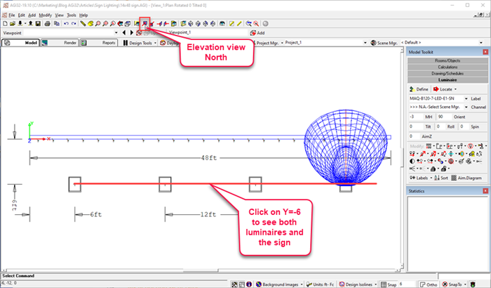
Here is the resultant view.
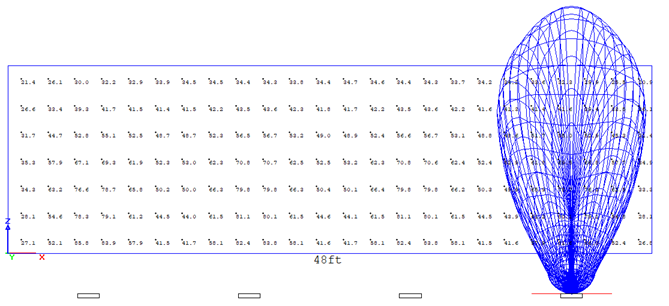
We could enable Isolines or use Highlight Values to better understand the illuminance gradient. Instead, let’s investigate in Render mode.
STEP 7 – Evaluate in Render Mode.
Use the Orbit command to look at the face of the sign. Use the mouse wheel to zoom out as if you where viewing from a distance (roll the wheel back). Notice the gradient of light across the sign.

Look at the sign in pseudocolor by clicking on the Pseudocolor button at the bottom of the screen.
Access the Pseudocolor Settings from the menu next to the button.
Check the “Apply Maximum” box for Illuminance. Set the field to 100 fc. Your visualization should look like ours below.
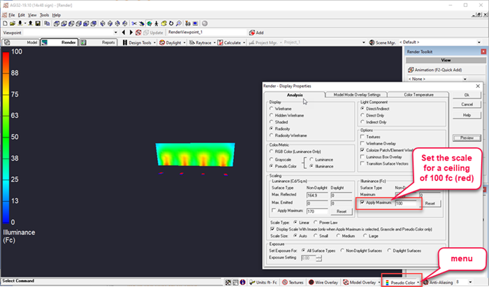
It’s interesting to turn pseudocolor off and on a few times to see if you see the correlation to the RGB image. Try changing the ceiling illuminance value to 50 (from 100). Now turn it off and on again. By effectively binning values over 50 you get a better correlation between pseudocolor and RGB than highlighting the small number of very high values.

STEP 8 – Add a Texture.
Let’s try another exercise in perception, add a photograph to the sign as a texture.
Return to Model mode. Select Surface Edit from the Rooms/Objects toolkit, the select the sign.
Make sure you highlight the front face (move the blue highlight as before).
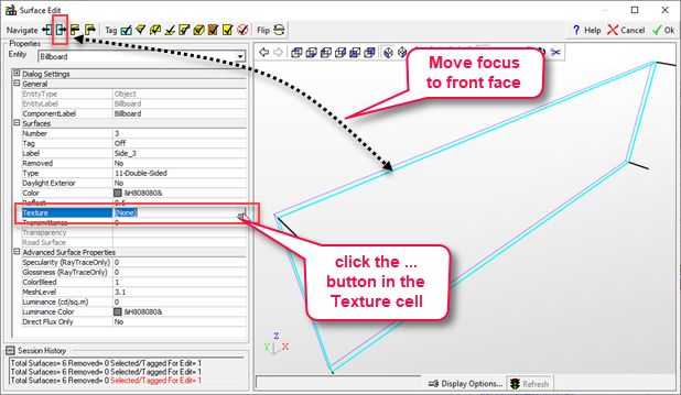
In the Textures dialog:
- Click on the Browse button.
- Locate an image on your computer system. For best results it helps if it has the same aspect ratio as our 48×14 sign. For the purposes of this exercise you can use anything.
- The new image will end up in the “Unclassified” section of the textures library.
- Select it and use the “Stretch” Display Mode.
- Click OK to exit the textures dialog and OK again the exit the Surface Edit command.
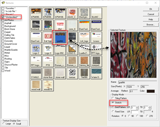
Adding a texture will change the reflectance of the sign surface (based on the average pixel color of the texture bitmap) so AGi32 will want to recalculate.
Click the calculate button to refresh the calculations. They won’t change by much as the only other surfaces exchanging light with the sign are the luminaire housings.
Go to Render Mode and click on the Textures button. How does your sign look now? Notice it is very difficult to discern the luminance gradient of the sign when your texture image is diverse like ours. If the image is mostly one color, the gradient of light will be easier to see.

Summary and thoughts…
That’s a decently deep dive into exterior sign lighting. Here are a few questions to entertain on your own and perhaps play with in your model.
- Outdoor advertising is not Dark Sky friendly. What happens if you light the sign from the top? You can easily do this by simply mirroring the luminaires through the center line of the sign (top to bottom). Then delete or turn off the bottom luminaires.
- Try experimenting with alternative luminaire positions: perhaps MH=-2 or -1, setback = 4 or 5. Can you improve the uniformity of the sign with out sacrificing to much light to the sky?
- How about lighting the sign from the ground if it is 10’ up? You would need a different luminaire but it might be fun to try floodlighting the sign from alternative positions. You will quickly discover how much light you loose to the surround. Try putting the whole model inside of a large room with all reflectance’s set to 0.01. See how much spill light you get from the sign. This is informative and you can understand why concerned stakeholders limit billboard lighting or ban it altogether.
