Why Coves?
Architectural features like Coves and Coffered ceilings afford the Lighting Designer an opportunity to light the Space and hide the Luminaries simultaneously. Cove lighting can be used for both ambient and task lighting while minimizing discomfort and disability glare potential. Revit’s modeling tools allow an easy avenue to incorporate Cove Lighting into a typical ElumTools work-flow.
Constructing the Cove
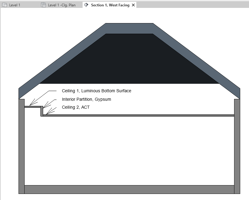
If you’re working with an Architectural model which already has the Cove construed this step can, of course, be skipped. But building a cove from scratch can also be done quickly, using the Revit modeling tools. Here’s a common technique, illustrated in Section.
- Start by construing the basic building geometry; Roof, Walls, and Floor. Skip the ceiling, for now.
- Create a Ceiling Element for the top of the Cove. This is “Ceiling 1” in the Section.
- Create a second Ceiling Element for the main Ceiling in the Room. This is “Ceiling 2” in the Section.
- Create an interior partition to join Ceilings 1 and 2.
Adding the Light
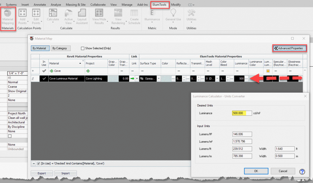
For most projects, lighting the Cove from here is a simple matter of adding Lighting Fixture Families and configuring properly in Luminaire Manager. Same procedure you would using for a typical ACT lighting solution. But a, perhaps less obvious, strategy is to assign a Luminous Material to the cove. Here’s the process.
- Add a Material to the Revit project with a descriptive name. Something like “Cove Luminous Material”. Don’t worry about assigning Revit Material Assets. These details will be handled in the ElumTools Material Mapping dialog.
- Assign an appropriate Luminance to the Material. This field is located in the “Advanced Properties” fly out of Material Mapping.
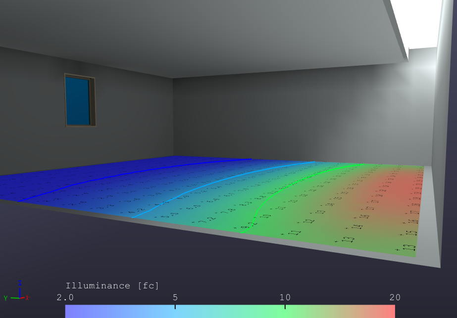
- Calculate! The Luminous Surface will illuminate the environment based on the specified Luminance value.


