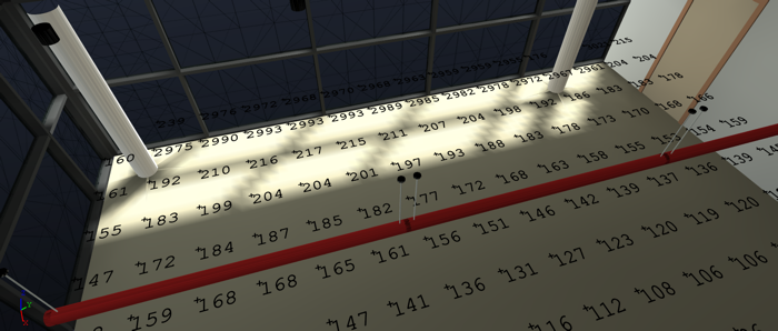
It is now possible to calculate daylight illuminance (fc or lux) in ElumTools 2014 (released 2014.4) using the familiar Room, Space or Selected Elements techniques. The electric lighting component can be included as well if desired. The current capability calculates results for a single date and time for your Revit project location, or any site you might elect to study using the Perez sky model and weather data published by the US-DOE.
To get started you will first need to install ElumTools 2014.4 (or later depending on when you read this) AND the separate weather database available from the ElumTools website. Assuming you are already well versed in ElumTools workflow, you obviously need to validate materials and luminaire families (if considering electric lighting) and place work plane calculation points.
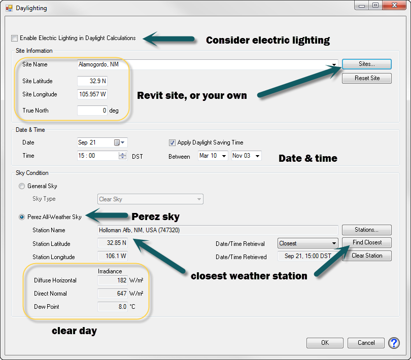
Now switch modes to Daylighting using the Modes menu which previously contained only General Use (electric) and Emergency modes. You will notice an additional button appears on the ribbon to set the “Daylight Parameters”. Click there and you will see your Revit project latitude and longitude shown. Don’t be alarmed if the True North angle seems odd. ElumTools uses a different coordinate system than Revit with Zero East and positive angles CCW. The Revit true north angle is automatically converted to the ET system in this dialog.
If you like, you can add your own site locations using the Sites button which can be useful if you want to quickly compare what your daylighting performance might be at another location without changing the Revit site. The Weather database allows you to easily locate latitude and longitude for the site location of your choice. It’s easy to reset to your Revit site by just clicking the Reset button.
Next, set your date, time and select the sky model. The IES and CIE sky models are included but the Perez model is required when using real weather data (LEED version 4, Nov 2013 release requires local weather data be used). Use the “Select Closest” button to load the weather station closest to your Revit project site location.
That’s it, unless you want to include electric lighting in the calculation in which case you must check the box at the top of the dialog. You can dim and switch your lights on an instance basis if desired when including electric lighting component from Revit Properties. LEED calculations stipulate daylight alone so playing with the electric contribution is for your own knowledge.
Once you close the dialog you are free to use any of ElumTools calculation options to compute daylight illuminance (single Room or Space, Multiple Rooms/Spaces or Selected Elements). If you have created Revit schedules for lighting results, they will now report daylight illuminance. You can switch back and forth between daylight and electric lighting results (or Emergency) using the Mode menu and results are maintained for each calculation type.
Watch the short video on YouTube (or elumtools.com) to see the step-by-step process.
Specifics:
You MUST set the visible transmittance of your glazing in ElumTools materials map. ElumTools collapses all multi-pane systems into a single “Daylight Portal” with Vt_total equal to the transmittance property set in the materials map. All glazing must be in an exterior wall/roof and should be oriented properly (exterior side out).
Caveats:
The current daylight implementation cannot consider exterior structural elements such as light-shelves or other exterior devices. It also cannot see any external structures such as the skyscraper across the street. We are working on conquering these details as we speak.


