Getting It Right
Ian Ashdown, P. Eng., FIES
Senior Scientist, Lighting Analysts Inc.
[Please send all comments to allthingslighting@gmail.com]UPDATE 16/07/08 – Added Optis SPEOS to list of validated (not “certified”) software products and Test Case 5.11 analysis.
In 2006, the Commission International de l’Eclairage (CIE) published CIE 171:2006, Test Cases to Assess the Accuracy of Lighting Computer Programs. To quote from the summary:
The objective of this report is to help lighting program users and developers assess the accuracy of lighting computer programs and to identify their weaknesses. A validation approach is therefore presented based on the concept of separately testing the different aspects of light propagation. To apply this approach, a suite of test cases has been designed where each test case highlights a given aspect of the lighting simulation domain and is associated with the related reference data.
Two types of reference data are used: data based on analytical calculation and data based on experimental measurements. The first is associated with theoretical scenarios that avoid uncertainties in the reference values. The second type is obtained through experimental measurements, where the scenario and the protocol are defined in a manner that minimizes the uncertainties associated with the measurements.
As one of the 24 members of CIE Technical 3-33 that wrote the report (mostly as a technical editor and reviewer), and also as a member of the IES Computer Committee that spent a decade attempting to write a similar document, I can attest that it was a monumental task. It is therefore understandable that there were at least a few errors in the final report.
The first and most important of these errors became apparent a year later when one of the first validations of a commercial lighting design and analysis program was conducted (Dau 2007). Further errors became evident during the preparation of a graduate thesis (Osborne 2012), and more during a recent validation study (Dau 2016).
Understanding and documenting these errors is important. To date, there have been at least fifteen lighting design and analysis programs that have been validated against some or all of the CIE 171:2006 test cases, including:
| Manufacturer | Program | Reference |
| Autodesk | 3ds Max Design | Osborne 2012 |
| APOLUX / LightTools | Carvalho 2009
Cunha 2011 Moraes 2013 Pereira 2008 |
|
| DIAL GmbH | DIALux / DIAL Evo | Mangkuto 2016 |
| EDSL | Tas Daylight | EDSL 2015 |
| LBNL | Radiance | Donn et al. 2007
Geisler-Moroder and Dur 2008 Osborne 2012 |
| Lighting Analysts | AGi32 / ElumTools | Dau 2007 |
| Lightscape Technologies | Lightscape | Maamari 2006 |
| Mental Images | mental ray | Labayrade and Fontyonont 2009 |
| nVidia | iRay | Dau 2016 |
| Optis | SPEOS | Labayrade and Sorèze 2014 |
| Relux | Relux | Maamari 2006 |
| Velux | Daylight Visualizer | Labayrade et al. 2009
Labayrade et al. 2010 |
NOTE: Some companies have stated that their products have been “certified” by the Ecole Nationale des Travaux Publics de l’Etat (ENTPE). The CIE Central Bureau has confirmed (Paul 2013) that it has requested these companies not to use the phrases “certified by” or “certified against” CIE 171:2006. (The correct terminology is “validated.”)
Unfortunately, the CIE has yet to publish errata for CIE 171:2006, and there are currently no plans to do so.
As a service to the lighting industry, then, the following is a complete list of known errors in CIE 171:2006. Hopefully, this information will ease the pain and suffering of anyone undertaking the work of validating a lighting design and analysis program against this document.
1. Test Case 5.7
The objective of Test Case 5.7, “Diffuse reflections with internal obstructions,” is to “verify the capability of a program to simulate the influence of an obstruction to diffuse illumination.”
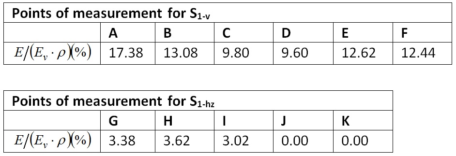
The derivation of Table 19 is not explained in CIE 171, but it was presumably determined using form factor analysis. The following independent analysis indicates that the values presented in Table 19 are incorrect.
1.1 Analytical Reference
As noted in Section 5.7.3, “To enable comparison between the simulation results and the analytical reference independently from the illuminance value over S2 or from its surface reflectance, the reference values are presented under the form of E / Ev· ρ (see Table 19). This is equal to the configuration factor between the measurement point and the unobstructed portion of S2.
1.2 Table 19 Analysis
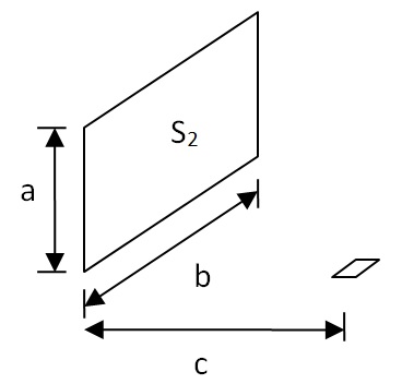
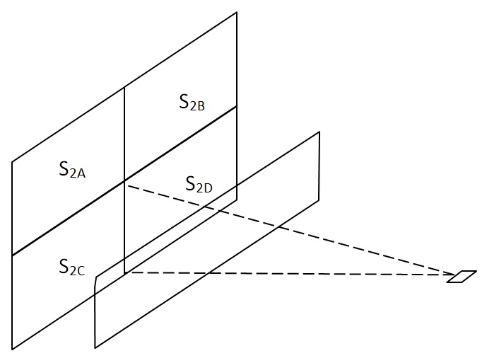
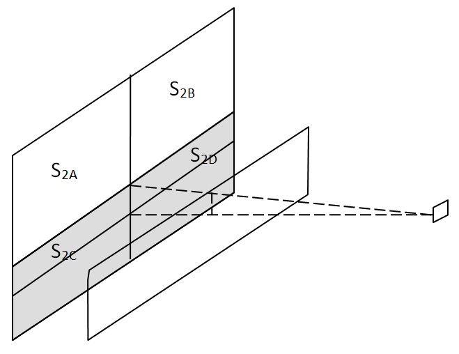
To validate the values presented in Table 19, it is necessary to calculate the configuration factors between the measurement point and the unobstructed portion of S2. For the horizontal surface S1‑hz measurements, the geometric relationships are:
and the configuration factor C is given by:
We can then use form factor algebra to determine:
and the configuration factor C is given by:
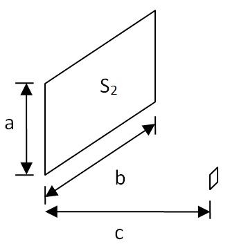
For the vertical surface S1‑v measurements, the geometric relationships are:
where:
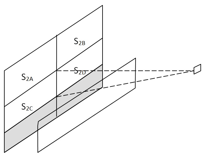
We can again use form factor algebra to determine:
where:
for measurement points A through D, and:
where:
for measurement points E and F.
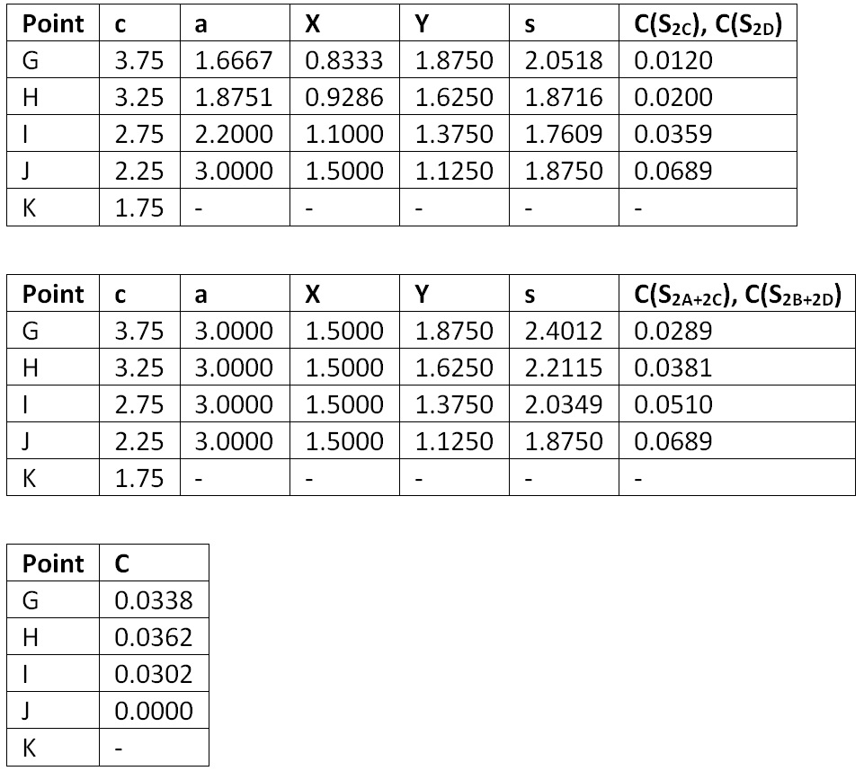
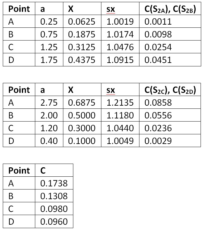
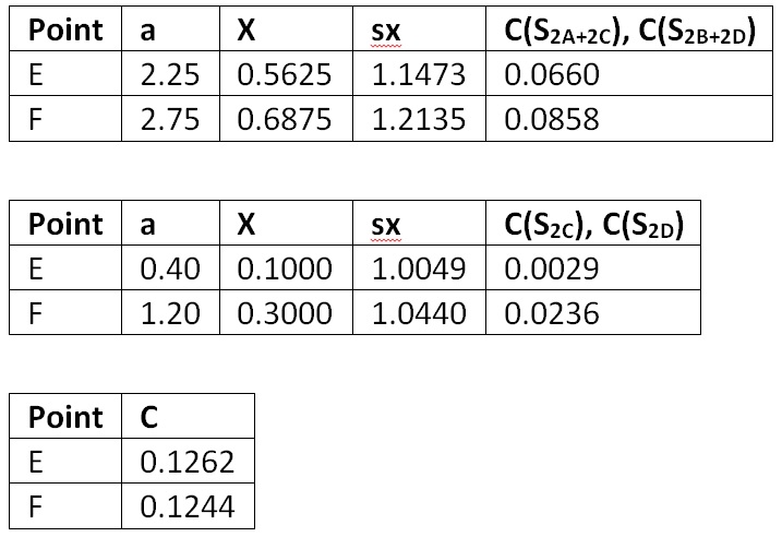
Table 19 then becomes:
1.3 Conclusion
Table 19 of CIE 171:2006 is incorrect, likely because incorrect geometry was used for the calculations.
1.4 Worksheet
Horizontal Points (G – K)
b = 2.0
Vertical Points (A – D)
b = 2.0
c = 4.0
Y = 0.5
sx = sqrt(1 + X2)
sy = sqrt(1 + Y2) = 1.1180
Vertical Points (E – F)
b = 2.0
c = 4.0
Y = 0.5
sx = sqrt(1 + X2)
sy = sqrt(1 + Y2) = 1.1180
2. Test Case 5.8
The objective of Test Case 5.8, “Internal reflected component calculation for diffuse surfaces,” is to “assess the accuracy of the diffuse inter-reflections inside a room.”
The approach consists of analytically calculating the indirect illuminance of a closed sphere by an isotopic point light source and using this as the “approximate average indirect illuminance” of a square room.
2.1 General Approach Commentary
To quote from CIE 171:2006:
The test case geometry is a square room of dimensions 4 m x 4 m x 4 m (ST = 96 m2), with all surfaces being uniform diffusers and spectrally neutral. An isotropic point light source is positioned at the centre of the room with an output flux (f) of 10000 lm.
The reflectance is the same for all interior surfaces and varies from 0% to 95%.
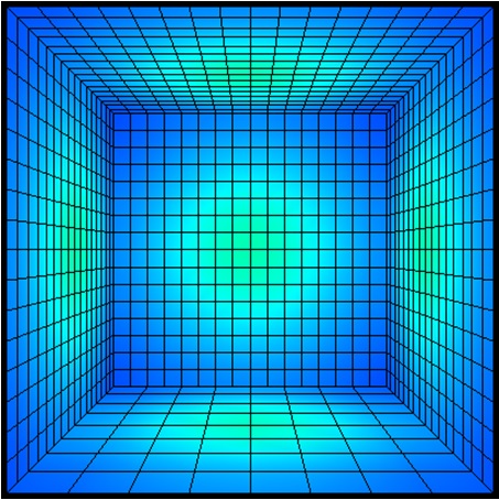
It is understandable that CIE 171:2006 specifies a square room rather than a tessellated sphere, as some older programs (such as Lighting Technologies’ Lumen Micro) are incapable of supporting arbitrarily oriented surface elements. However, this presents a problem in that the interreflections between surface elements at the room corners result in significantly lower illuminances for these elements than for those elements in the middle of the room surfaces. This problem is exacerbated by low surface reflectances[1]. (See Figure 1 for an example.)
This problem is compounded by the choice of surface discretization. A coarse mesh will tend to smooth the illuminance distribution, but it will also mask errors. Without specifying a mesh resolution or how to average the results, it is difficult to compare the results from different lighting design programs that use the radiosity method. It is even more difficult to compare results from ray-tracing programs, as the results depend on the number of stochastically traced rays.
Figure 1. Example room with 10% surface reflectance. Illuminance values range from 48 cd/m2 in room corners to 209 cd/m2 in center of room surfaces. (Table 1 predicts 115 cd/m2.)
2.2 Analytical Solution Commentary
To quote again from CIE 171:2006:
Analytically, in the case of a closed sphere with diffuse internal surfaces, the indirect flux incident upon an internal point of the sphere is given by the equation:
where:
Φ = direct luminous flux entering the sphere.
The indirect illuminance at any internal point of the sphere is given by the equation:  (15)
(15)
where:
E = indirect illuminance (lx);
ST = sphere internal surface (m2);
ρ = sphere internal surface reflectance;
Φ = direct luminous flux entering the sphere (lm)
The problem with this approach is that most lighting design programs do not separately report direct and indirect illuminance. It is therefore necessary to relate total illuminance to its indirect component for the special case of an integrating sphere.
The luminance L at any internal point of the sphere due to indirect and direct illuminance is:
Given that the sphere surface is an ideal diffuse reflector, the luminous exitance M at any point is:
and so the illuminance E at any point is:
The direct illuminance at any point is:
and so its indirect illuminance is:
and so:
Dividing each entry of Table 20 by gives:
Table 1. Illuminance variation with reflectance.
2.3 Conclusions
In view of the above, it is recommended that:
- The test case geometry be amended to consist of a sphere rather than a square room; and
- The test case analytical reference be amended to specify total illuminance rather than indirect illuminance.
3. Test Case 5.9
The objective of Test Case 5.9, “Sky component under a roof unglazed opening and the CIE general sky types,” is to “test the capability of a lighting program to calculate the sky component under different conditions, in particular those standardized by the CIE general sky.”
3.1 Correction
With respect to Section 5.9.3, the entries for CIE General Sky Type 3 in Table B1 are transposed; the correct values are:
4. Test Case 5.10
The objective of Test Case 5.10, “Sky component under a roof glazed opening,” is to “verify the capability of a lighting program to simulate the influence of glass with a given directional transmittance under different type of CIE general skies.”
4.1 Analysis
The glazing consists of 6mm clear glass, whose average transmittance is not specified. However, an equation for glass transmittance is given by Mitalas and Arseneault (1968):
where q is the incidence angle. By setting q to zero, the calculated transmittance T is 0.878.
5. Test Case 5.11
The objective of Test Case 5.11, “Sky Component and external reflected component for as façade unglazed opening” is to “verify the capability of a program to correctly calculate the contribution of the external ground and the sky luminance distribution to the internal illuminance of a room with a faced opening.”
Unfortunately, this test case is flawed in that “the external ground illuminance is assumed to be uniform.” This assumption fails to take into consideration shadowing of the ground by the building. Quoting further, “the direct sun illuminance is not taken into consideration,” so the shadowing will depend on the CIE sky type. (Whether this assumption significantly affects the published results in Tables B.9, B.10, and B.11 is unknown.)
6. Test Case 5.12
CIE 171:2006 does not state the transmittance of 6mm clear glass. However, following Test Case 5.10, it should be assumed to be 0.878.
7. Test Case 5.13
The objective of Test Case 5.13, “SC+ERC for an unglazed façade opening with a continuous external horizontal mask” is to “verify the capability of a lighting program to simulate the influence of an external horizontal mask on the internal direct illuminance.”
Unfortunately, this test case is fundamentally flawed for three reasons:
- it assumes an external horizontal mask of uniform luminance Lob, which is derived in Section 5.13.1.1 from the external horizontal ground illuminance. It does not, however, consider the shadowing influence of the black room beneath it.
- It does not specify the mask surface reflectance rob.
- It requires the mask to have uniform luminance. However, the shadowing influence of the black room will result in a nonuniform luminance distribution.
Given these flaws, Tables B.21, B.22, and B.23 should not be used.
This test case should be restated such that the mask surface reflectance rob is zero, in which case the tables will have to be recalculated.
8. Test Case 5.14
The objective of Test Case 5.14, “SC+ERC for an unglazed façade opening with a continuous external vertical mask,” is to “verify the capability of a lighting program to simulate the influence of an external vertical mask on the internal direct illuminance.”
Unfortunately, this test case is fundamentally flawed for three reasons:
- It assumes an external vertical mask of uniform luminance Lob, which is derived in Section 5.14.1.1 from the external horizontal ground illuminance. It does not, however, consider the shadowing influence of the black room in front of it.
- It does not specify the mask surface reflectance rob.
- It requires the mask to have uniform luminance. However, the shadowing influence of the black room will result in a nonuniform luminance distribution.
Given these flaws, Tables B.24, B.25, and B.26 should not be used.
This test case should be restated such that the mask surface reflectance rob is zero, in which case the tables will have to be recalculated.
Acknowledgements
Thanks to Dawn De Grazio (Lighting Analysts Inc.) and Wilson Dau (Dau Design and Consulting Inc.) for assistance in preparing this article.
References
Carvalho, C. R. 2009. Avaliação do programa APOLUX segundo protocolos do relatório CIE 171:2006 referentes à illuminação natural. Dissertation, Federal University of Santa Catarina, Florianopolis (in Portuguese).
Cunha, A. V. L. 2011. Avaliação do programa APOLUX segundo os protocolos de modelos de céu do relatório técnico CIE 171:2006. Dissertation, Federal University of Santa Catarina, Florianopolis (in Portuguese).
Dau, W. 2007. Validation of AGi32 Against CIE 171:2006. Dau Design and Consulting Inc.
Dau, W. 2016. Personal communication. Dau Design and Consulting Inc.
Donn, M., D. Xu, D. Harrison, and F. Maamari. 2007. “Using Simulation Software Calibration Tests as a Consumer Guide – A Feasibility Study Using Lighting Simulation Software,” Proc. Building Simulation 2007, pp. 1999-2006.
EDSL. 2015. Validation of TAS Daylight against CIE 171:2006. Environmental Design Solutions Limited.
Geisler-Moroda, D., and A. Dur. 2008. “Validation of Radiance against CIE 171:2006 and Improved Adaptive Subdivision of Circular Light Sources,” Proc. Seventh International Radiance Workshop.
Labayrade, R., and M. Fontoynont. 2009. “Use of CIE 171:2006 Test Cases to Assess the Scope of Lighting Simulation Programs,” CIE Light and Lighting.
Labayrade, R., H. W. Jensen, and C. Jensen. 2009. “Validation of Velux Daylight Visualizer 2 against CIE 171:2006 Test Cases,” Proc. Building Simulation 2009, pp. 1506-1513.
Labayrade, R., H. W. Jensen, and C. Jensen. 2010. “An Iterative Workflow to Assess the Physical Accuracy of Lighting Computer Programs,” Light and Engineering 18(2):66-70.
Labayrade, R., and T. Sorèze. 2014. Assessment of SPEOS Against CIE 171:2006 Test Cases. Ecole Nationale des Travaux Publics de l’Etat (ENTPE).
M. S. Langer. 1999. “When Shadows Become Interreflections,” International Journal of Computer Vision. 34 (2/3):193-204.
Maamari, F., M. Fontoynont, and N. Adra. 2006. “Application of the CIE Test Cases to Assess the Accuracy of Lighting Computer Programs,” Energy and Building 38(7):869-877.
Mangkuto, R. A. 2016. “Validation of DIALux 4.12 and DIALux evo 4.1 against the Analytical Test Cases of CIE 171:2006,” Leukos 12(3):139-150.
Mitalas, G. P., and J. G. Arseneault. 1968. Division of Building Research Computer Program No. 28: Fortran IV Program to Calculate Absorption and Transmission of Thermal Radiation by Single and Double Glazed Windows. Ottawa, ON: National Research Council of Canada.
Moraes, L. N., A. S. da Silva, and A. Claro. 2013. “Evaluation of the Software LightTool and APOLUX according to Protocols of Technical Report CIE 171:2006,” Proc. Building Simulation 2013, pp. 1079-1086.
Osborne, J. 2012. Building a Comprehensive Dataset for the Validation of Daylight Simulation Software, using Complex “Real Architecture.” MSc. Thesis, Victoria University of Wellington.
Paul, M. 2013. Personal communication.
Pereira, R. C. 2008. Avaliaçã de ferramentas de simulação de illuminação natural por meio de mapeamento digital del luminânacias da abóboda celeste e entorno. Thesis, Federal University of Santa Catarina, Florianopolis (in Portuguese).
[1] In general, the luminance distribution of a non-convex object is determined not only by external illumination but also by interreflections between its surfaces. This issue has been extensively studied in the field of computer vision and image understanding. See, for example, Langer (1999).

