I had an opportunity to assist our tech-support team recently with a few people on vacation. During that time, I assisted with three cases of “dark” renderings. If that happens in one week I thought, how often do we deal with this issue? A quick search of support tickets pulled up a large number of these incidents, and thus, fuel for a new blog topic!
The majority of these issues appear to happen out of the blue from the user’s perspective; “It was fine and then I made a simple change and the rendering was dark! Help!”.
First let’s clarify “dark”. It does not typically mean black as in no light, although that is possible. The rendering usually appears more like all sources are dimmed dramatically, but some may not be visible at all.
The underlying problem – Very high maximum scene luminance
AGi32 renderings are scaled based on the maximum calculated surface luminance in the scene. Imagine that this value becomes the “white point” where all surface appearances are then scaled downward from there. A sudden change in max surface luminance rescales the rendering.
There are several common problems that can create the “dark” condition. Here are simple recreations of the three different issues I observed.
Case #1 – Source inside an object
On large exterior projects it’s easy to accidentally place a wall mounted luminaire inside of a structural object. This typically blasts the backside (inner surface of the wall) with light, resulting in very high luminance on the inside of the wall (remember, objects are composed of two-sided surfaces).
Compare the two renderings below:
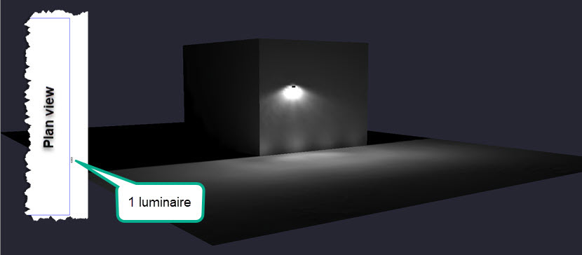
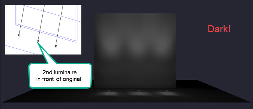
One luminaire on the face of the wall.
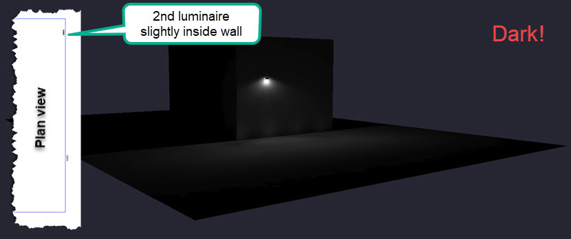
Next, a second luminaire is accidentally added just behind the wall. Not only does the second luminaire fail to appear, it warps the scaling of the rendering with the super high luminance on the inside of the wall, so the original luminaire appears to be dimmed.
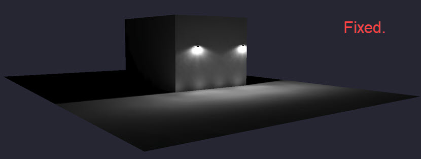
Situation fixed by moving the luminaire to the front side of the wall.
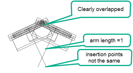
Case #2 – Close proximity of luminaire symbols
Case #2 is essentially the same problem, but now the very high luminance occurs on an adjacent luminaire symbol (all symbols are physical objects in Full Radiosity Mode). We see this most often with floodlights pointing into one another. It’s easy to ignore that an adjacent symbol might be interfering with light from another, but it’s common!
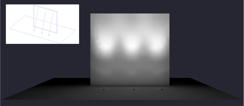
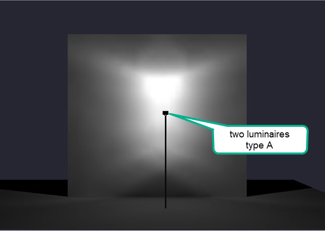
Here are three floodlights aimed at a vertical surface. Notice the overall brightness of the rendering.
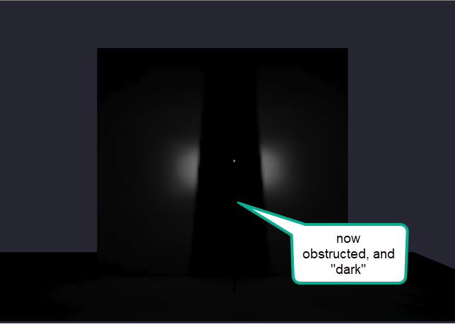
Subsequently, after adding a second row of floodlights just in front of the originals, the rendering goes “dark”. There are now six luminaires but the second set of three are too close to the originals and receive a blast of direct light to the back of the symbol. This changes the maximum surface luminance in the scene and rescales the rendering. Notice you can even see the reflected light on the ground from the back of the symbol (below).
The obvious fix is to separate the luminaires by a larger distance and check aiming. Make sure the symbol size and luminaire placement are accurate.
Case #3 – Change in size of the luminaire luminous dimensions
This is the least obvious and most complicated example. Imagine that you have been using an IES file from manufacturer A. You have “Smart Symbols” enabled in AGi32 when you select the IES file. You don’t pay much attention and select a Box_Down symbol. IMPORTANT! You may not realize that the Smart Symbols procedure will automatically size the render version of the symbol correctly for the “luminous dimensions” as read from the IES file.
For the purposes of presentation, you might swap the Model symbol for something different like “Flood-3” shown below. You include a 1’ Arm in the definition to simulate a bracket as they are mounted on a pole. And… even though you were sloppy about placing the fixtures, things are working out ok.
Now, you would like to change that fixture to a different IES file from manufacturer B. You create a new luminaire definition, click through the Smart Symbols dialog again selecting the Box_Down symbol (just like last time). Then you use the Luminaire Swap command to exchange A for B.
Ah oh… The rendering goes dark! What happened? Everything is the same but the IES file!
Not exactly.
When you loaded the new luminaire from manufacturer B, the Smart Symbols procedure sized the Render version of the symbol correctly for the new IES file’s luminous dimensions. The render symbol is now much larger. IMPORTANT: Remember, Model symbols are just line data, but Render symbols are physical objects.
The size of the luminous area is obtained from the manufacturer’s IES file. In the case of manufacturer A, the luminous dimensions are entered as zeros in the IES file. AGi32 sees this as a point source, bumps each dimension to 0.1 in each direction for technical reasons, AND, sizes the Render symbol accordingly. In this case of A, the Render symbol is super small and the fixtures DO NOT obstruct one another in Render Mode, even though they appear to do so in Model mode!
When the swap is made to manufacturer B, the new render symbol is true size per the IES file and now the render symbols overlap and obstruct one another. Bingo – a dark rendering.
Bottom line, the inaccurate luminous dimensions are BAD practice on the part of the manufacturer. Bad, bad…
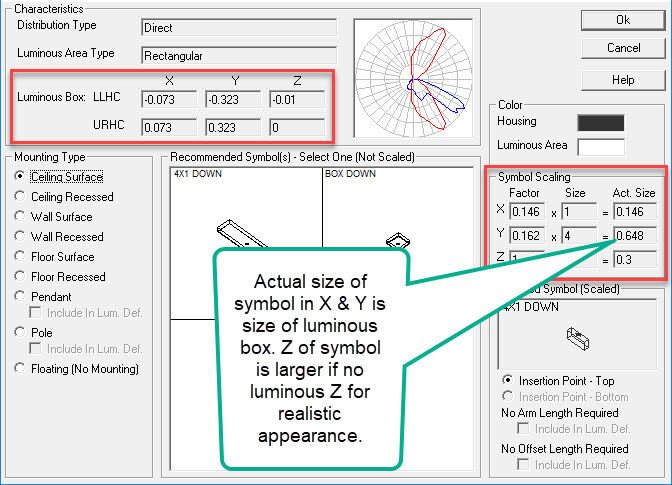
Where can you find the luminous size information in AGi32? It is shown as the “Luminous Box” in the Smart Symbols dialog (below) where you can also observe the scaling of the symbols and the luminaire definition. Dimensions can also be seen in the Define dialog.
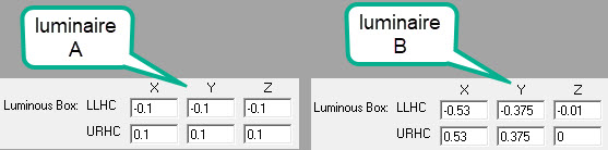
See the comparison in luminous sizes between our two example luminaires below.
How can you correct this? Pay close attention to the luminous box in the Smart Symbols dialog when bringing in the IES file. Observe how it scales the selected symbol. If it is not correct, you can resize the symbol in the Render Symbol dialog and correct the luminous box in the Define dialog.
Of course, be careful when placing luminaires!
Further on luminous dimensions…
Historically, some testing laboratories (typically internal, not independent) assumed that all outdoor luminaires are essentially point sources for the purposes of calculation, therefore the luminous dimensions are not important and are carelessly entered (0,0,0). Unfortunately, software uses this information when luminaires are close to surfaces as it is important to know the size of the luminous area! This might be a wall mounted luminaire for example. It is also fairly common to see the luminous dimensions entered in the IES file as the overall fixture dimensions. This is obviously a problem as well, especially for interior luminaires. It’s a good idea to make a habit of checking the luminous box information for all IES files. Let the manufacturer know when you find bad data.