It might seem silly to talk about ElumTools 2014 after the 2015 release, but we communicate with Revit users all the time who are still in the 2013 world, or (gasp…) even earlier. While we are not so naïve as to think that Revit users might upgrade their projects from older versions to 2014 or 2015 for ElumTools alone, however, if lighting is important, there are some very compelling improvements that were implemented in the ElumTools 2014 framework that deserve attention.
Prior to the release of ElumTools 2014.2 we had been using Revit’s Room and Space boundary tools to find geometry (walls, floors, etc). This worked fine for basic environments with flat ceilings. However, it was not always suitable for more complicated architectural environments. Missing walls, ceilings and more were fairly common. Realizing this was unacceptable, and with a little help from the Revit 2014 API, we got smart and essentially rewrote the boundary tools to look for all geometry essential for lighting calculations. The result is a substantial improvement in ElumTools functionality.
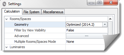
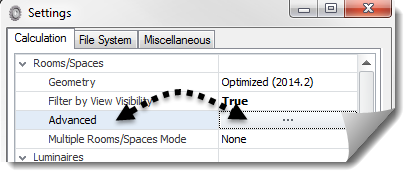
Opening the Settings dialog in ElumTools 2014 we see the Calculation tab (Fig 1). Gone are the old settings under “Rooms/Surfaces” of “Include Hosted Elements” and “Include Room/Space Contents”. In their place we have “Filter by View Visibility” and an “Advanced” button. Sounds complicated… and it can be. But the good news is, the defaults are very good and seldom do you need to use the Advanced button.
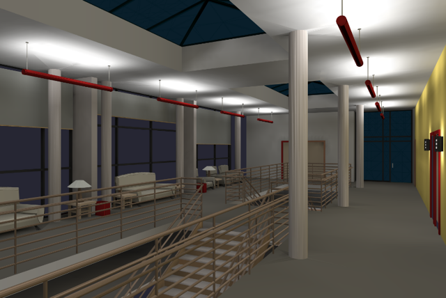
What did we gain? How about this (Fig 2):
Notice immediately, ElumTools is picking up the system families: stairs and railings. Then, by ensuring that the room definition has suitable upper and lower boundaries, you can get geometry for multiple floors and sloped elements such as the skylight glazing. None of this was possible prior to ElumTools 2014.2. Note: the decimal point in the program version is important. This denotes the second release of the 2014 version. The 2014.1 release is simply 2013 reincarnated for 2014 Revit.
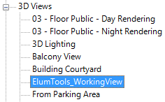
Let’s look at the new filter by view visibility option. In the new Optimized (2014.2) mode of operation (default), all geometry that is visible in the 3D View titled “ElumTools_WorkingView” (created automatically) will be considered in the calculation of the selected area: Room or Space (Fig. 3).
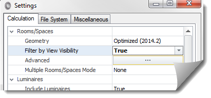
This loses the simplicity of turning off furniture with the old Room/Space contents switch, but it adds lots of flexibility in that you can filter out anything you like from the calculations by simply hiding it in the ElumTools_WorkingView. This might not only be furniture, but small details such as plumbing fixtures or plants. To use the Filter by View setting, open the ElumTools Settings dialog and switch the “Filter by View Visibility” to True (Fig. 4). Then use Revit’s Visibility Graphics system to filter the view before running your calculations.
So what’s behind the “Advanced” button? (Fig.5) As mentioned previously in this post, the defaults are adequate for most environments, but that said, there are a few cases where you may need to make an adjustment to ensure ElumTools can see all of the necessary geometry.
The Advanced settings have two distinct behaviors: the ability to increase the size of the room/space calculation volume (top portion of the dialog), and the ability to assign a specific treatment to some geometric components (lower portion). In both cases, the goal is to enable the ElumTools room/space calculation volume to include the geometry that you want, and perhaps omit portions that you do not.
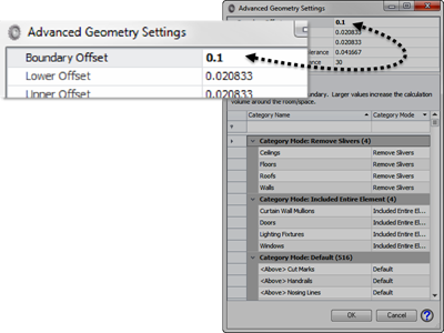
The top section of the dialog is simple: increase the value used for “Offset” to expand the calculation volume (Boundary, Upper, Lower)(Fig. 6). The idea here is some geometric elements that are important to the calculation may lie outside the volume entirely (do not intersect).
An example would be the glazing in a curtain wall. In order to allow ElumTools Room/Space boundaries to find this important element (especially for daylighting), we can expand the “Boundary Offset” from the default value (0.020833) by a small amount to intersect the curtain glazing (change to 0.1). See the example below (Fig. 7).
One – This room contains a curtain wall. Two – With the default settings we see no glass, and thus, no daylight! Three – Adjust the Boundary offset to 0.1 and now we have glass, and light!
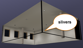
The lower portion of the dialog provides control over the treatment of specific categories of geometry (and more) contained in the Revit project (once again, the defaults are typically adequate). When the calculation volume is increased to help find intersecting geometry (the Boundary Offset), it may leave small “slivers” of geometric elements that are now captured within the expanded boundary, but are outside of the actual volume created by the intersection of all the elements such as ceiling, walls, and floor (Fig. 8). It is nice to be able to remove these excess portions of geometry that have no impact on the computations from the visualization (and calculation). Bring on the “Remove Slivers” option!
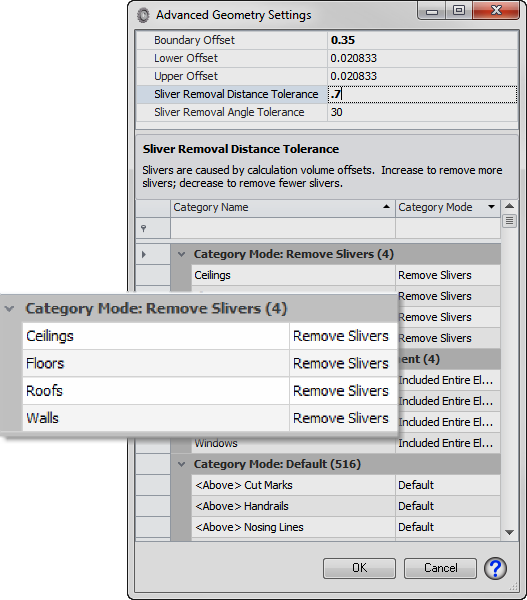
In development we identified several categories that always needed special treatment for slivers (ceilings, floors, roofs, walls). These categories are shown in the dialog and assigned “Remove Slivers” by default (Fig. 9).
However, it is possible when setting the Boundary Offset to a larger value (0.35 for example) that you may defeat the sliver removal process due to the “Sliver Removal Tolerance” being too small (also Fig. 9). The solution is to simply increase the “Sliver Removal Distance Tolerance”. A value double the Boundary Offset is usually sufficient.
In a slightly different use case, some categories require special treatment in order to capture the entire element. This is typical of a category such as Curtain Wall Mullions where the boundary intersects the element but does not capture all surfaces. These categories are assigned the property “Include Entire Element” by default. You will notice in the renderings of our daylight room above, the mullions are extending beyond the room when viewed from outside, this is the result of the capture entire element behavior.
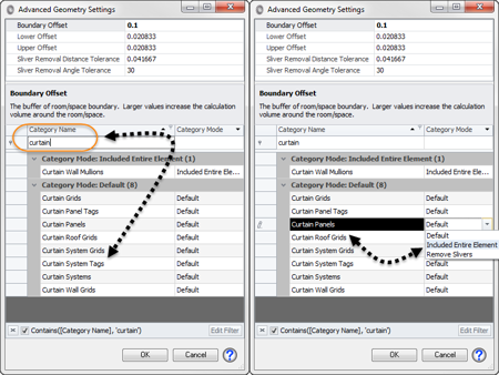
Given the two behaviors: “Remove Slivers” and “Include Entire Element”, you may find cases in your projects where some geometric elements are either creating slivers, or, are not being captured by ElumTools. To assign a behavior, locate the category in the list by using the filter, then assign it the desired property.
For example: in Figure 10 below we have searched for all categories that contain the text “curtain”. The results are shown. We can then select the behavior for the desired category from the pull down menu.
As you might expect, some of these things are subject to “Trial and Error”. Hopefully, you can dial-in your results quickly!

