A few things have changed in the new version 20 Define dialog since the previous pre-release blog post and video. In this post we’ll look at the things that are “slightly” different for the release v20 software.
Symbol Terminology
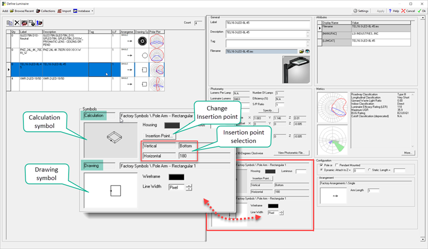
Terminology – after making much needed modifications to the way the software handles symbol insertion point, we realized that the old Model and Render terminology for symbols was less descriptive than desired. We wanted terms that intuitively described the symbol functions.
Model is now Drawing – Symbol representation in Model mode is always a line drawing. It has no calculational implications (no change there). Plus, we have a special “drawing only” set of symbols (that you can amend) to either match CAD drawings and/or internal practices or standards.
Render is now Calculation – This is the big one. The render symbol has always had calculational implications in terms of size, shape, symbol insertion point and photometric center. With our newly implemented Insertion Point options this is now more transparent to the user and more important.

By default, the Drawing and Calculation symbols are linked. You will select a Calculation symbol when defining a luminaire in the Smart Symbols dialog. You can separate the symbol representations between Drawing and Calculation from the Symbols dialog by clicking in either the Drawing or Calculation symbol cells in the Define dialog, then checking the “Different Drawing Symbol” box in the Symbols dialog.

Smart Symbols & Mounting Type Options
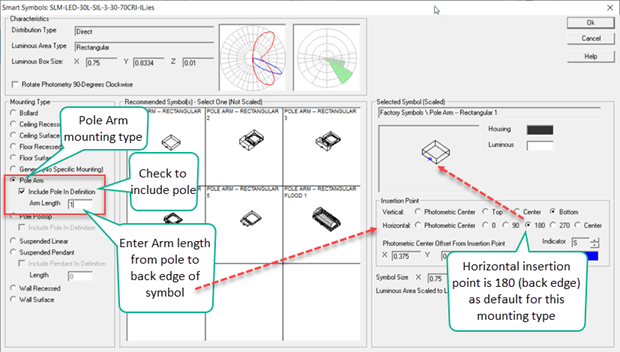
We expanded the Mounting Type options in Smart Symbols to allow for Poles, Arms and Pendants to be defined up front, rather than having to do it in the main dialog. This also dovetails into the insertion point options as the default (and best choice) insertion point may change depending on the selection of Mounting type. Arm length is now the actual length of the Arm from pole to insertion point.

The software no longer includes a recommended Arm length as in version 19 (and earlier). The old Arm included the distance from the symbol insertion point and a minimum was required to move the attachment outside of the symbol (not intuitive). The Arm is now the distance from pole to back edge of symbol when the default insertion point of 180 is used for Pole Arm mounting type. This is more predictable and precise.
Symbol Insertion Point Options
AGi32 version 20 now supports options for both vertical and horizontal insertion point positions. The defaults for these positions will change when presented in Smart Symbols based on the Mounting Type selected. For example, as shown above, the default insertion point for Pole Arm mounting is Vertical=Bottom, Horizontal=180 (degrees). The Arm will then attach to the bottom of the symbol on the rear edge. The numeric response to the Horizontal insertion point are in degrees from due East (like Orient) with the luminaire facing East.
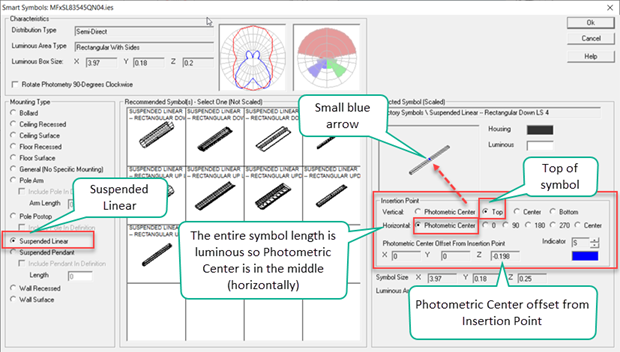
Let’s look at a different example, a linear pendant. With the Suspended Linear Mounting Type selected the insertion point defaults are Vertical=Top, Horizontal=Photometric Center.

What does this mean in terms of Mounting Height of the luminaire as entered in the Luminaire Toolkit? The Mounting Height references the location of the symbol insertion point. In the case of our suspended linear pendant, this would reference the top of the symbol. So where exactly is the photometric center?
Location of Photometric Center
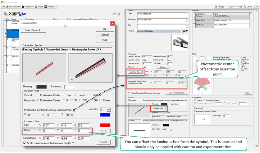
The Photometric Center is always placed in the center of the luminous area of the Calculation Symbol and the luminous portion of the symbol is sized to match the luminous area in the IES file. This was not very transparent in previous releases. With version 20 you might have noticed the X,Y,Z “Photometric Center Offset from Insertion Point” in the Smart Symbols dialog above. In the case of our linear pendant, the Photometric Center is located -0.198 feet (units are feet) below the insertion point. This is also shown in the main Define dialog Photometry section (below). Clicking on the buttons for either Luminous Box (Photometry Section) or Insertion Point (Symbols Section) you can access the sub-dialog that also contains all of this information.

Ultimately, through the options afforded to Insertion Point, symbol choice and size, and the scaling of the luminous area to the Luminous Box from the IES file, you have control over the location of Photometric Center. The location of Photometric Center can now also be scheduled!
As a final variable that should be used only through careful understanding and experimentation, you can now offset the luminous box from the symbol. This moves the location of the Photometric Center and has obvious calculational implications. As a potential application, consider a surface mounted luminaire where a luminous side is directly adjacent to the surface. You can move the luminous box away from the surface slightly and have better visualization and allow the radiosity mesh to account for the proximity of source and surface.
Full vs Direct Calculation Mode
In version 19 (and prior) the location of photometric center was slightly different for Direct calculation and Full radiosity calculation methods. This could result in small calculation differences for models with no reflectance considerations when computed by the Direct and Full engines.
For v19 (and earlier) the photometric center was at the insertion point for Direct calculation mode. For Full radiosity the photometric center was the center of the luminous box which was located at the center of the (formerly) Render symbol luminous area. For version 20, the photometric center is now at the center of the luminous box for the Drawing (formerly model) symbol as well making the two symbols agree on photometric center position.
File Compatibility
As you have probably gathered, these are important changes from previous versions of AGi32. As you might image, there can be some file compatibility issues to be aware of. We have published a Knowledgebase article for assistance.
