AGi32’s symbols library is by no means able to cover the variety of shapes encountered in today’s modern luminaire design market. However, you may not realize it is quite easy to create custom symbols within AGi32 to meet your needs.
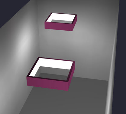
Let’s create an open rectangular symbol with luminous inside surfaces like those shown below.
We will need to use two objects to construct the symbol.
Make the “Height of Sides” 0.5 feet (6” tall).
Change the cursor Snap setting to 0.1
Draw the shape below. Be sure to include the two break-points where shown in the illustration. This will be important going forward.
Now create the second object to fill in the open side.
Tag all of the interior surfaces. Use the Navigate button to move the surface selector, press the F8 key to select and move on.
Make sure you have the four surfaces selected as shown below (DO NOT select the small surfaces created by the break-points).
With the four interior surfaces selected, change the Luminance to one (1). When we use the Create Symbol command this change will indicate that these surfaces are to appear luminous.
To be efficient, you could remove the two sliver surfaces created by the break-points making the symbol ever so slightly less “heavy” (select them and enable the removed property). It’s not very important in this example, they are two small surfaces so this step is skipped.
Exit Surface Edit and go to Plan view.
Use the All (or Window) options and select the objects.
The command will prompt for the symbol “insertion point”. Set the point at Z=0 in the middle of the symbol as shown.
In the subsequent dialog (below), leave the default selection of “Model and Render” selected. If you want to use a different symbol in Model Mode for some applications, you can change it. Most likely you will use it in both modes.
You can create one with the button. It will be created here: C:\ProgramData\AGi32\Symbols
You can now select the symbol for any luminaire definition by clicking in the Render or Model symbol cells in Luminaire Define, select the folder where you put it and locate the symbol.
You may be tempted to try and import 3D DWG models for custom symbols. This can be done, however, you must be VERY careful to avoid surface heavy models (lots of surfaces). Best practice dictates that you *simplify* the models in the source software radically BEFORE you import them to AGi32. Radiosity calculations are sensitive to surface count. If you are using a symbol with 1000 surfaces (or worse) you will slow down your computations drastically. Also, realize that fancy pole mounted symbols are seldom visible unless there is light coming from above them.